Frequency Combs
An optical frequency comb is a set of mutually coherent spectral lines whose frequencies lie on an affine grid,
The spacing and common offset are radio or microwave frequencies even when is hundreds of terahertz. Measuring and controlling those two coordinates turns a broadband optical spectrum into a phase-coherent ruler between microwave and optical frequencies.
The formula is simple; using it correctly is not. One must know the tooth index and beat-note sign, preserve coherence during spectral broadening, measure both comb coordinates, control cycle slips and path noise, and state which external reference supplies accuracy. A comb transfers and divides phase. It does not create an accurate frequency reference by itself.
Canonical Scope
Section titled “Canonical Scope”This page owns:
- the derivation of the comb spectrum from a phased pulse train;
- the physical meaning and measurement of ;
- carrier-envelope phase slip and ;
- octave-spanning -to- self-referencing;
- absolute optical-frequency measurement and tooth-index assignment;
- simultaneous stabilization of the two comb degrees of freedom;
- transfer-oscillator combinations and optical frequency division;
- comb noise, cycle slips, path noise, and counter conventions;
- the role of combs in optical clocks and precision spectroscopy;
- the current relation between optical standards and the SI second.
Mode Locking owns pulse-train formation, active and passive locking, pulse duration, chirp, and pulse diagnostics. Linewidth and Coherence owns single-line phase diffusion and frequency-noise conventions. Laser Stabilization owns generic discriminators, feedback sensitivity functions, stability margins, and out-of-loop validation. Precision Spectroscopy owns atomic references, systematic shifts, Allan deviation, and uncertainty budgets. The present page owns the phase-coherent frequency link among those systems.
Convention Ledger
Section titled “Convention Ledger”Unless stated otherwise:
- is ordinary frequency in hertz and is angular frequency;
- is the interval between equivalent output pulses;
- ;
- is the signed carrier-envelope phase advance per pulse under the field convention used below;
- is chosen in the standard interval ;
- is an integer tooth index, usually of order to for femtosecond laser combs;
- a heterodyne beat is reported as a nonnegative magnitude, while a separate sign records which side of the tooth contains the continuous-wave laser;
- linewidth, instability, and uncertainty are distinct quantities.
Changing the carrier-phase convention changes the sign assigned to and may replace by . Measured tooth frequencies are unchanged when the indexing convention is transformed consistently.
Comb Spectrum
Section titled “Comb Spectrum”From a periodic pulse train
Section titled “From a periodic pulse train”Let be the complex positive-frequency field of one pulse, including its local carrier. Consider an infinite train
The factor says that successive pulses have the same envelope but a fixed carrier-envelope phase increment. With the Fourier convention
translation gives
Using
the spectrum is nonzero at frequencies satisfying
Therefore
with
The single-pulse spectrum supplies the broad spectral envelope. Timing periodicity and carrier-envelope slip supply the line positions. A smooth broadband spectrum is not automatically a metrological comb; the individual components must retain a predictable phase relation.
Finite observation and finite coherence
Section titled “Finite observation and finite coherence”The delta functions above assume infinitely many identical pulses. A finite record of pulses replaces each delta function by a narrow Dirichlet-kernel feature with width of order
Timing jitter, carrier-envelope phase noise, amplitude noise, cavity drift, and environmental perturbations further broaden or pedestal the teeth. A comb tooth can be much narrower than the passive cavity resonance because active phase locking correlates pulse-to-pulse phase, but “equally spaced” does not imply zero linewidth.
The affine grid has an indexing freedom
Section titled “The affine grid has an indexing freedom”The representation
is unchanged under
Choosing fixes this bookkeeping freedom. It does not determine the large absolute index of an observed optical tooth. That requires a coarse optical-frequency measurement or another known reference.
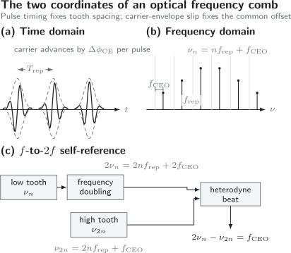
The pulse interval fixes , while the carrier-envelope phase advance fixes the common offset . In an octave-spanning comb, doubling a low tooth and beating it against the high tooth cancels the large index term and returns .
Repetition Rate
Section titled “Repetition Rate”Group-delay origin
Section titled “Group-delay origin”Let be the total spectral phase accumulated in one cavity round trip, including propagation and dispersive mirror phases. Cavity resonances obey
Linearizing around a carrier gives
where
is the round-trip group delay. Adjacent resonances are separated by
Thus repetition rate is fundamentally a group-delay quantity. Mirror motion, refractive-index changes, air pressure, temperature, and intracavity dispersion can all perturb it.
Photodetection
Section titled “Photodetection”A sufficiently fast photodiode detects the intensity pulse train. Its radio-frequency spectrum contains components at
The fundamental or a high harmonic can be compared with an electronic reference. High harmonics can improve phase sensitivity but demand detector bandwidth, sufficient signal-to-noise ratio, and control of amplitude-to-phase conversion.
Photodetection measures pulse timing, not . Two combs can have identical intensity pulse trains and different carrier-envelope offsets.
Fundamental and harmonic operation
Section titled “Fundamental and harmonic operation”One pulse per cavity round trip gives the fundamental repetition rate. A harmonically mode-locked cavity can contain equally spaced pulses and produce an intensity repetition frequency . The optical comb spacing then depends on the actual temporal periodicity and phase relation of the full field. Multiple pulses with unequal phase or amplitude can generate substructure rather than one clean enlarged spacing.
Carrier-Envelope Offset
Section titled “Carrier-Envelope Offset”Phase-delay origin
Section titled “Phase-delay origin”The envelope returns after the group delay , while the carrier accumulates the round-trip phase . With the convention used above, the carrier-envelope slip is
This exposes the difference between phase and group propagation. In a nondispersive idealization they can coincide modulo ; in a real ultrafast oscillator, material dispersion, mirror phase, self-phase modulation, gain dynamics, and pulse energy affect the slip.
The offset frequency is the residual obtained by extending the comb grid toward zero index:
It is not the optical carrier frequency, not the pulse repetition rate, and not the absolute carrier-envelope phase of one isolated pulse. It is the rate at which the carrier-envelope phase advances through the pulse train.
Why ordinary detection cannot see it
Section titled “Why ordinary detection cannot see it”Square-law photodetection of a single pulse train removes a common optical phase. It readily yields mode differences such as
but the offset cancels. To measure one must compare optical components related by a known nonlinear frequency ratio or use an external optical reference.
Self-Referencing
Section titled “Self-Referencing”Octave-spanning f-to-2f method
Section titled “Octave-spanning f-to-2f method”Suppose the comb contains tooth at the low-frequency edge and tooth at the high-frequency edge:
Frequency doubling the low tooth gives
Heterodyning it with the high tooth yields
The enormous term cancels electronically. An octave is needed because the high optical frequency must be twice the low one. In practice, nonlinear fiber or a waveguide often broadens the oscillator spectrum before second-harmonic generation and heterodyne detection.
What self-referencing establishes
Section titled “What self-referencing establishes”Self-referencing measures the offset against the comb’s own line grid. It does not by itself:
- lock ;
- determine the absolute tooth index;
- prove that the broadened spectrum preserves coherence everywhere;
- stabilize ;
- supply traceability to the SI;
- eliminate optical-path or counter errors.
After detection, a phase-locked loop can compare with a radio reference and drive an actuator. Alternatively, the offset can be measured and included in a transfer-oscillator combination without forcing it to be quiet.
Coherent broadening
Section titled “Coherent broadening”An octave of optical power is insufficient if nonlinear propagation adds uncorrelated phase noise. Pulse-energy fluctuations can convert through self-phase modulation, Raman response, polarization effects, or coupling noise into comb-phase fluctuations. The -to- beat signal-to-noise ratio, linewidth, and out-of-loop optical comparisons test whether the broadened portions remain useful.
Other schemes, including -to- comparison, can use less than one octave at the cost of additional nonlinear conversion. Difference-frequency generation can produce an offset-free comb in which the common offset cancels, but the resulting system still needs a complete frequency and noise accounting.
Measuring an Optical Frequency
Section titled “Measuring an Optical Frequency”Beat against the nearest tooth
Section titled “Beat against the nearest tooth”Let a continuous-wave laser at beat with tooth . The detector gives a radio-frequency magnitude
Introduce to record the side of the tooth:
Every term on the right must be known at a common measurement epoch. The beat sign can be found by deliberately tuning the continuous-wave laser or a comb coordinate and observing the beat direction.
Assigning the integer index
Section titled “Assigning the integer index”A coarse wavemeter, known atomic transition, calibrated spectrometer, or second comb supplies an estimate . For an unambiguous nearest-tooth assignment, the combined coarse uncertainty should usually be less than , with margin for the beat sign and possible mode hops.
An incorrect index changes the inferred optical frequency by , often hundreds of megahertz. A beautiful narrow beat note does not protect against this discrete error.
Sensitivity to the two coordinates
Section titled “Sensitivity to the two coordinates”Small comb-coordinate changes move tooth by
Since is large, a small repetition-rate error can become a large optical error. This is not amplification of fractional instability: when the comb is coherently referenced, the same fractional phase relation is transferred across the frequency ratio. It does mean that absolute-frequency noise and counter resolution must be propagated with the factor .
Stabilization
Section titled “Stabilization”Two coordinates, at least two error signals
Section titled “Two coordinates, at least two error signals”For a mode-locked laser comb, controlling two independent frequencies fixes the affine tooth grid. Common choices are:
- lock to a microwave reference and to another radio-frequency reference;
- lock one optical tooth to a narrow optical reference and lock ;
- lock two separated optical teeth to two optical references;
- measure all relevant signals and cancel comb noise with transfer-oscillator electronics.
The first choice transfers microwave stability upward. The second divides optical stability downward. The third constrains both grid coordinates optically. The fourth can compare references without requiring the free comb to be quieter than they are over the full measurement band.
Actuator cross-coupling
Section titled “Actuator cross-coupling”Let and be two actuator coordinates, such as cavity length and pump power. Linearized response has the form
Cavity length often acts strongly on , while pump power or intracavity loss often acts strongly on through pulse energy and nonlinear phase. Neither actuator is perfectly orthogonal. Stable control may require matrix decoupling, bandwidth separation, feedforward, or multiple fast and slow actuators.
In-loop and out-of-loop evidence
Section titled “In-loop and out-of-loop evidence”An in-loop error signal can be small because the servo forces that detector to agree with its set point. It does not expose errors common to the reference and detector, an unmonitored optical path, counter configuration, or a cycle slip.
Independent evidence includes:
- an out-of-loop beat against another stabilized comb;
- redundant counters with different implementations;
- simultaneous beats at separated optical wavelengths;
- a second -to- interferometer;
- logged actuator range and lock status;
- cycle-slip detectors;
- closure of an optical-frequency ratio or frequency loop.
Cycle slips
Section titled “Cycle slips”A phase lock loses an integer number of cycles when its beat signal becomes too weak or its phase excursion exceeds the tracking range. The resulting record can contain a discrete frequency-count error even though the lock immediately recovers.
Cycle-slip risk increases with poor heterodyne signal-to-noise ratio, polarization drift, amplitude dropouts, excessive servo error, and counter dead time. Long measurements should report slip detection and data-rejection criteria rather than assuming continuous lock from an averaged spectrum.
Transfer Oscillators and Frequency Ratios
Section titled “Transfer Oscillators and Frequency Ratios”Suppose two optical references satisfy
Form
The repetition-rate term cancels exactly. Combining the two beats with the measured offset cancels both internal comb coordinates. This is the transfer-oscillator principle: the comb can transfer a frequency ratio even when its free-running noise is larger than the desired comparison, provided all signals are sampled synchronously with sufficient bandwidth and the electronic scaling is accurate.
Digital implementations must handle time alignment, finite counter bandwidth, quantization, latency, sign conventions, and the exact rational mode-number ratio. “Comb noise cancels” is a statement about a specified combination, not a blanket property of raw counter streams.
Optical Frequency Division
Section titled “Optical Frequency Division”Lock tooth to an optical reference with fixed signed beat . Then
Photodetection converts this repetition rate or one of its harmonics into a microwave output. Ideally, division by reduces absolute phase-frequency fluctuations while preserving fractional instability:
Residual noise arises from the comb locks, photodetection, optical-path length, amplitude-to-phase conversion, shot noise, electronics, and reference distribution. The comb is therefore an optical divider, while the ultrastable laser and atomic transition provide the high-frequency reference.
The reverse operation is optical synthesis: microwave-referenced and define optical tooth frequencies, and a continuous-wave laser can be phase locked at a chosen offset from one tooth.
Optical Clocks and Precision Spectroscopy
Section titled “Optical Clocks and Precision Spectroscopy”Clock architecture
Section titled “Clock architecture”An optical atomic clock contains several conceptually distinct elements:
- an atomic or ionic transition that defines the reference frequency;
- a narrow-linewidth local oscillator interrogating that transition;
- a servo that steers the local oscillator to the atomic resonance;
- a comb that divides or compares the optical frequency;
- counters, time transfer, and uncertainty evaluation that connect the result to other standards.
The comb is clockwork, not the pendulum. It phase-coherently links frequency domains but does not remove atomic systematic shifts, local-oscillator noise, dead time, relativistic redshift corrections, or time-transfer uncertainty.
Absolute measurements and optical ratios
Section titled “Absolute measurements and optical ratios”An absolute optical-frequency measurement references the comb, directly or through a calibrated chain, to the SI second. An optical ratio compares two optical references through the comb. Ratios can avoid some limitations of a microwave flywheel and are central to consistency tests among different clock species and to searches for variations of fundamental constants.
Frequency ratios still require:
- correct tooth indices and beat signs;
- synchronous counting or transfer-oscillator cancellation;
- stabilized optical paths;
- gravitational-potential accounting when clocks are at different heights;
- evaluated systematic shifts in both references;
- transparent treatment of correlations.
Current status of the SI second
Section titled “Current status of the SI second”As of July 2026, the SI second remains defined by fixing the unperturbed ground-state hyperfine transition frequency of caesium-133 at
Several optical frequency standards have lower evaluated uncertainties than the best caesium realizations and are used as secondary representations of the second. That performance has motivated the BIPM and the Consultative Committee for Time and Frequency to pursue a redefinition roadmap. The published BIPM timetable describes 2026 as the earliest proposal stage and 2030 as the earliest ratification stage; an optical redefinition has not yet replaced the caesium definition.
This distinction matters. A record optical-clock comparison can surpass the realization accuracy of caesium while its traceable absolute frequency is still expressed in the present SI second.
Comb spectroscopy
Section titled “Comb spectroscopy”A comb can also interrogate many transitions simultaneously. Its advantages include broad coverage, resolved and calibratable teeth, high spatial coherence, and compatibility with enhancement cavities or dual-comb down-conversion. The sample response, tooth power, detector dynamic range, pressure and Doppler broadening, cavity dispersion, and line-shape model still determine spectroscopic accuracy.
Precision Spectroscopy develops reference transitions, line centers, systematic corrections, stability, and uncertainty. Ultrafast Spectroscopy Overview owns time-domain pump–probe and nonlinear applications.
Other Comb Architectures
Section titled “Other Comb Architectures”The affine frequency-grid concept is broader than one laser design.
- Mode-locked laser combs obtain broad spectra from periodic ultrashort pulses. Their natural coordinates are repetition rate and carrier-envelope offset.
- Electro-optic combs generate sidebands from a continuous-wave carrier using phase or intensity modulation. The optical carrier and microwave drive set the grid.
- Microresonator combs use parametric four-wave mixing in a nonlinear resonator. Soliton states can connect pulse and frequency-domain pictures, but pump detuning, thermal dynamics, mode crossings, and large line spacing require architecture-specific control.
- Difference-frequency and harmonic combs translate a parent comb to other spectral regions, with offsets transformed by the nonlinear frequency relation.
Not every comb emits isolated short pulses, and not every regularly spaced spectrum has the coherence needed for metrology. The operational test is whether each relevant line can be assigned a stable frequency and phase relation with an adequate uncertainty budget.
A Measurement Workflow
Section titled “A Measurement Workflow”- Define the frequency equation. State tooth-index, offset, and beat-sign conventions.
- Measure the repetition rate. Identify the detected harmonic, reference, bandwidth, and counter mode.
- Measure the offset. Specify the self-referencing scheme, optical bandwidth, beat signal-to-noise ratio, and lock or correction method.
- Assign the tooth index. Use an independent coarse optical frequency with enough margin to exclude neighboring indices.
- Determine the beat sign. Tune a known actuator and observe the direction of change.
- Stabilize or synchronously sample. Match servo bandwidths and counter timing to the intended noise cancellation.
- Control optical paths. Stabilize or bound phase noise between the reference, comb, sample, and detector planes.
- Detect slips and mode hops. Use redundant channels and preserve raw diagnostics.
- Propagate uncertainty. Include references, counters, synthesis, path transfer, and correlations.
- Close the loop independently. Compare with another comb, ratio, or known transition whenever the claimed accuracy warrants it.
Common Mistakes
Section titled “Common Mistakes”- The spacing determines every tooth. It does not; the common offset is also required.
- Self-referencing locks the comb. It measures ; feedback or post-processing must use that measurement.
- An octave-spanning spectrum guarantees coherence. Broadband power and broadband phase coherence are different claims.
- A narrow optical beat identifies the absolute frequency. The tooth index and beat sign can still be wrong.
- The comb creates clock accuracy. Accuracy comes from the external atomic, optical, or microwave reference and its evaluated transfer.
- Only one actuator affects each coordinate. Real comb controls are cross-coupled.
- A quiet in-loop spectrum proves a quiet output. Common-path errors, path noise, and slips can be invisible in loop.
- Comb teeth all move equally. Offset changes move them equally; repetition-rate changes scale with .
- Fractional and absolute noise scale the same way under division. Optical division reduces absolute frequency fluctuation while ideally preserving fractional instability.
- Counters always sample simultaneously. Triggering, gate definitions, dead time, and latency must be checked.
- The SI second is already optically defined. Optical standards have surpassed caesium realizations, but the current definition remains caesium-based as of July 2026.
Exercises
Section titled “Exercises”1. Derive the tooth frequencies
Section titled “1. Derive the tooth frequencies”Starting from
derive the allowed spectral frequencies.
Solution
Fourier transformation gives
The sum is nonzero as a distribution when
With ,
Reducing the second term modulo defines . Thus
The pulse spectrum weights the line amplitudes but does not alter this ideal affine grid.
2. Phase slip to offset frequency
Section titled “2. Phase slip to offset frequency”A comb has and a carrier-envelope phase advance per pulse. Find in the standard interval.
Solution
Use
Therefore
This already lies between and .
3. Self-reference algebra
Section titled “3. Self-reference algebra”An octave-spanning comb contains and . Show that the beat between and is independent of and .
Solution
The two frequencies are
Subtraction yields
The cancellation is why the offset becomes electronically measurable. The result still depends on coherent nonlinear conversion and sufficient heterodyne signal-to-noise ratio.
4. Absolute optical frequency
Section titled “4. Absolute optical frequency”A comb has
A continuous-wave laser lies above tooth . Find the laser frequency.
Solution
Because the laser is above the tooth, :
The tooth frequency is
Therefore
Choosing the wrong beat sign would shift the answer by ; choosing the neighboring tooth would shift it by .
5. Coordinate-noise sensitivity
Section titled “5. Coordinate-noise sensitivity”For tooth , suppose and . Find the tooth shift if the two fluctuations add with the same sign.
Solution
Use
Then
The repetition-rate term dominates the absolute shift because of the large index. If the fluctuations are stochastic, their covariance rather than a simple same-sign sum determines the variance.
6. Tooth-index requirement
Section titled “6. Tooth-index requirement”A comb has . A coarse wavemeter gives an optical frequency with standard uncertainty . Is this nominally sufficient to identify the nearest tooth? What additional checks remain?
Solution
Half the tooth spacing is
The uncertainty is smaller, so it is nominally sufficient with useful margin if the wavemeter is unbiased and the laser does not hop. One must still determine the heterodyne beat sign, include the wavemeter calibration uncertainty and drift, verify and at the same epoch, and exclude mode hops during the measurement.
7. Optical frequency division
Section titled “7. Optical frequency division”An optical reference at controls tooth , with the offset and signed beat corrected to zero. Find . If the optical reference has fractional frequency fluctuation , what ideal absolute fluctuation appears on ?
Solution
The divided frequency is
Ideal coherent division preserves fractional fluctuation:
Thus
This value is the ideal transferred fluctuation. Real photodetection, servo, path, and electronic noise add residuals.
8. Transfer-oscillator cancellation
Section titled “8. Transfer-oscillator cancellation”Two optical references obey
Construct a radio-frequency combination that equals and contains no term.
Solution
Multiply the first relation by and subtract it from the second:
The terms cancel exactly. The right-hand side is synthesized from measured radio-frequency signals. Accurate cancellation requires synchronous sampling, correct signs and indices, sufficient bandwidth, and accurate implementation of the rational factor .
References
Section titled “References”- Th. Udem, J. Reichert, R. Holzwarth, and T. W. Hänsch, “Accurate measurement of large optical frequency differences with a mode-locked laser,” Optics Letters 24, 881–883 (1999), doi:10.1364/OL.24.000881.
- J. Reichert, R. Holzwarth, Th. Udem, and T. W. Hänsch, “Measuring the frequency of light with mode-locked lasers,” Optics Communications 172, 59–68 (1999), doi:10.1016/S0030-4018(99)00491-5.
- D. J. Jones et al., “Carrier-envelope phase control of femtosecond mode-locked lasers and direct optical frequency synthesis,” Science 288, 635–639 (2000), doi:10.1126/science.288.5466.635.
- S. A. Diddams et al., “Direct link between microwave and optical frequencies with a 300 THz femtosecond laser comb,” Physical Review Letters 84, 5102–5105 (2000), doi:10.1103/PhysRevLett.84.5102.
- R. Holzwarth et al., “Optical frequency synthesizer for precision spectroscopy,” Physical Review Letters 85, 2264–2267 (2000), doi:10.1103/PhysRevLett.85.2264.
- J. Reichert et al., “Phase coherent vacuum-ultraviolet to radio frequency comparison with a mode-locked laser,” Physical Review Letters 84, 3232–3235 (2000), doi:10.1103/PhysRevLett.84.3232.
- Th. Udem, R. Holzwarth, and T. W. Hänsch, “Optical frequency metrology,” Nature 416, 233–237 (2002), doi:10.1038/416233a.
- H. R. Telle, B. Lipphardt, and J. Stenger, “Kerr-lens, mode-locked lasers as transfer oscillators for optical frequency measurements,” Applied Physics B 74, 1–6 (2002), doi:10.1007/s003400100735.
- S. T. Cundiff and J. Ye, “Colloquium: Femtosecond optical frequency combs,” Reviews of Modern Physics 75, 325–342 (2003), doi:10.1103/RevModPhys.75.325.
- J. L. Hall, “Nobel lecture: Defining and measuring optical frequencies,” Reviews of Modern Physics 78, 1279–1295 (2006), doi:10.1103/RevModPhys.78.1279.
- P. Del’Haye et al., “Optical frequency comb generation from a monolithic microresonator,” Nature 450, 1214–1217 (2007), doi:10.1038/nature06401.
- T. Fortier and E. Baumann, “20 years of developments in optical frequency comb technology and applications,” Communications Physics 2, 153 (2019), doi:10.1038/s42005-019-0249-y.
- S. A. Diddams, K. Vahala, and T. Udem, “Optical frequency combs: coherently uniting the electromagnetic spectrum,” Science 369, eaay3676 (2020), doi:10.1126/science.aay3676.
- Bureau International des Poids et Mesures, “Resolution 5 of the 27th CGPM: On the future redefinition of the second” (2022), doi:10.59161/CGPM2022RES5E.
- Bureau International des Poids et Mesures, “Frequently Asked Questions concerning the Redefinition of the Second”, version 2.0, accessed 23 July 2026.
- National Institute of Standards and Technology, “Femtosecond-Laser Frequency Combs for Optical Clocks”, updated 26 March 2025.