G. P. Thomson Experiment
G. P. Thomson’s electron-diffraction experiments sent cathode rays, now understood as electron beams, through thin films and recorded ring patterns on a photographic plate. The result complemented the Davisson–Germer Experiment: electrons behaved as material particles in production and detection, but their propagation through ordered matter showed wave-like diffraction governed by de Broglie’s relation
The experiment is historically memorable because J. J. Thomson had helped establish the electron as a particle, while his son G. P. Thomson helped establish electron diffraction. That family contrast is a useful story, but the scientific point is sharper: independent diffraction geometries agreed with the same wavelength-momentum law.
Experimental Setup
Section titled “Experimental Setup”Thomson’s route used relatively fast electrons transmitted through very thin films. A typical schematic contains four parts:
- an electron source and accelerating voltage;
- collimation to make a narrow beam;
- a thin film or foil acting as the diffracting sample;
- a photographic plate or screen downstream of the film.
For an electron accelerated through a potential difference , the nonrelativistic kinetic-energy estimate is
Thomson’s transmission experiments used higher electron energies than the low-energy nickel-surface scattering in Davisson–Germer. At kilovolt-scale voltages, the wavelength is much smaller than an atomic spacing, so diffraction angles are small. A useful relativistic correction is
For the historical conclusion, the crucial observable was not merely that electrons passed through or scattered from the film. It was that the recorded intensity had concentric rings whose radii scaled as a diffraction pattern should when the electron wavelength was changed.
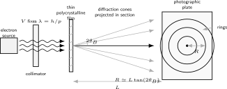
In a thin-film electron-diffraction geometry, many microscopic crystal orientations produce cones of diffracted electrons. A downstream plate cuts those cones in concentric rings, whose radii encode the de Broglie wavelength and lattice spacings.
Diffraction Rings
Section titled “Diffraction Rings”The ring pattern is the central signature of Thomson’s setup. In a single well-oriented crystal, diffraction may appear as spots or angular maxima tied to particular reciprocal-lattice directions. In a polycrystalline film, many small crystallites have different orientations. Each set of lattice planes that satisfies a Bragg condition sends electrons onto a cone around the incident beam. The photographic plate intersects the cones as rings.
In a simplified Bragg picture,
where is a lattice-plane spacing and is the Bragg angle. The diffracted beam is deflected by approximately from the incident direction. If the plate is a distance from the film, the radius of a ring is approximately
For small diffraction angles,
This last expression explains the basic experimental test. Increasing the accelerating voltage increases the momentum and decreases , so ring radii should shrink. Changing the film changes the relevant values, so the ring pattern should change in a way connected to the sample structure.
Wave Interpretation
Section titled “Wave Interpretation”The wave interpretation is not that the electron is a little classical ripple of charge passing continuously through every atom in the foil. The modern statement is that the electron state has phase. A periodic arrangement of scatterers adds amplitudes coherently in selected directions.
For elastic diffraction, the reciprocal-lattice form of the condition is
where and are incident and outgoing electron wave vectors and is a reciprocal-lattice vector. In a randomly oriented polycrystalline film, the possible directions are distributed around the beam axis, producing rings rather than a single set of spots.
The measured intensity is a probability pattern:
where is a scattering amplitude for arrival at radius on the plate. The plate records localized interactions, but the distribution of many electrons reveals the phase structure of the quantum state.
Relation to J. J. Thomson
Section titled “Relation to J. J. Thomson”J. J. Thomson’s cathode-ray work at the end of the nineteenth century helped identify the electron as a subatomic charged particle. G. P. Thomson’s thin-film diffraction experiments then showed that those same electrons could produce wave-diffraction patterns.
The historical contrast should not be read as a contradiction between two experiments. It shows why classical categories were too rigid. The electron is not sometimes an ordinary particle and sometimes an ordinary wave. It is a quantum object whose preparation, propagation, and detection require a formalism with states, amplitudes, and measurement probabilities.
The 1937 Nobel Prize in Physics recognized C. J. Davisson and G. P. Thomson for the experimental discovery of electron diffraction by crystals. The pairing matters: two independent experimental routes made the case much stronger than either route alone.
Evidence for Matter Waves
Section titled “Evidence for Matter Waves”Thomson’s experiment strengthened the matter-wave hypothesis in several ways.
First, it used transmission through thin films rather than reflection-like scattering from a nickel surface. This reduced the possibility that the Davisson–Germer result was an idiosyncrasy of one apparatus, one target, or one angular convention.
Second, the ring geometry was visually close to X-ray powder diffraction. Electrons, which had been treated as charged material particles, were producing patterns naturally interpreted with wavelengths and lattice spacings.
Third, the wavelength scale agreed with the de Broglie relation. The electron momentum came from the accelerating voltage, while the diffraction ring radii were read from the plate. Agreement between those independent quantities was the evidential core.
The combined lesson of Electron Diffraction, Davisson–Germer scattering, and Thomson thin-film rings is that wave-like propagation is not confined to light. Matter beams can interfere and diffract, while still being detected as discrete localized events.
What the Experiment Does Not Show by Itself
Section titled “What the Experiment Does Not Show by Itself”- It does not show that electrons are classical extended waves of charge.
- It does not by itself derive the Time-Dependent Schrödinger Equation.
- It does not make the simple Bragg formula an exact theory of electron diffraction through real films.
- It does not eliminate the need for coherence, collimation, sample thinness, and careful control of inelastic scattering.
- It does not replace the modern scattering-amplitude description used in detailed diffraction theory.
Those cautions are not weaknesses of the experiment. They keep the historical result in its correct scope: a powerful confirmation of matter waves, not a complete standalone foundation for all of quantum mechanics.
Common Mistakes
Section titled “Common Mistakes”- Saying J. J. Thomson proved the electron was a particle and G. P. Thomson proved it was a wave. The better statement is that quantum electrons show particle-like detection and wave-like propagation.
- Treating rings as mysterious circular paths. The rings are the intersection of diffraction cones with a detector plane.
- Forgetting the role of many crystallite orientations in a thin film.
- Applying the nonrelativistic wavelength formula blindly at high accelerating voltages.
- Confusing diffraction from a polycrystalline film with a two-slit interference experiment. Both involve phase, but the geometries and evidence are different.
- Reading the Bragg formula as a complete dynamical theory of electron scattering.
Cross-Links
Section titled “Cross-Links”- Matter Waves and Wave Mechanics
- de Broglie Matter Waves
- Electron Diffraction
- Davisson–Germer Experiment
- Double-Slit Experiment
- Experiment Index
- Momentum Eigenstates
- Plane Waves and Delta Normalization
- Wave Packets
- Fourier Wave Packets
- Scattering Amplitude
- Probability Amplitudes
References
Section titled “References”- G. P. Thomson and A. Reid, “Diffraction of Cathode Rays by a Thin Film,” Nature 119, 890, 1927, DOI: 10.1038/119890a0.
- G. P. Thomson, “Experiments on the Diffraction of Cathode Rays,” Proceedings of the Royal Society A 117, 600-609, 1928, DOI: 10.1098/rspa.1928.0022.
- G. P. Thomson, Electron Diffraction, Nobel Lecture, 1937.
- Nobel Prize Outreach, The Nobel Prize in Physics 1937.
- L. de Broglie, “Recherches sur la théorie des quanta,” Annales de Physique 10, 22-128, 1925, DOI: 10.1051/anphys/192510030022.
- C. Davisson and L. H. Germer, “Diffraction of Electrons by a Crystal of Nickel,” Physical Review 30, 705-740, 1927, DOI: 10.1103/PhysRev.30.705.
- M. Jammer, The Conceptual Development of Quantum Mechanics, 2nd ed., American Institute of Physics, 1989.
Exercises
Section titled “Exercises”- A nonrelativistic electron is accelerated through . Estimate its de Broglie wavelength using with in volts.
Solution
Substitute :
This is much smaller than a typical lattice spacing, so the diffraction angles are small. A relativistic correction is modest but not conceptually negligible at sufficiently high voltages.
- In a thin-film diffraction setup, take , , and . Estimate the first-order small-angle ring radius.
Solution
For small angles,
With ,
So the first ring radius is about .
- Why does a polycrystalline thin film tend to produce rings rather than a small number of isolated diffraction spots?
Solution
A polycrystalline film contains many microscopic crystallites with different orientations. For a fixed plane spacing and wavelength, each suitable orientation can diffract into a direction satisfying the Bragg condition. Rotating those directions around the incident beam forms a cone; the detector plane cuts the cone as a ring.
- Explain why Thomson’s experiment and the Davisson–Germer experiment were complementary evidence for matter waves.
Solution
Davisson and Germer used low-energy electrons scattered from a nickel crystal, while Thomson used transmitted electrons through thin films. The apparatus, sample geometry, and recorded pattern were different, but both connected electron momentum to diffraction through . Agreement in independent geometries made the matter-wave interpretation harder to dismiss as an apparatus-specific effect.