Single-Qubit Gates
Short Definition
Section titled “Short Definition”An ideal single-qubit gate is a unitary operator
acting on a chosen two-dimensional computational basis
It changes amplitudes, relative phases, or both. On the Bloch sphere, every one-qubit unitary acts as a proper three-dimensional rotation. Conversely, every proper rotation of the Bloch sphere is represented by two special-unitary matrices, and , and by infinitely many matrices if arbitrary global phases are retained.
This page is the canonical guide to the common gate families , , , , , , , and ; their exact matrices and Bloch actions; phase conventions; arbitrary one-qubit synthesis; and the distinction between a logical gate and its physical realization. Circuit Model owns circuit semantics and resource accounting, Bloch Sphere for Quantum Information owns the operational state geometry, and Spin Rotations derives the – relationship.
Fix the Convention First
Section titled “Fix the Convention First”Basis and action
Section titled “Basis and action”Unless stated otherwise, matrices below use the ordered computational basis
and act on state columns from the left. If a diagram applies and then , its matrix is
The rightmost factor acts first. A change of computational basis changes every displayed matrix by conjugation, so a gate name without a basis convention is incomplete.
Three notions of equality
Section titled “Three notions of equality”For gate calculations, distinguish:
- Exact matrix equality: .
- Equality up to global phase: .
- Equality as an isolated quantum channel:
The second implies the third. It does not permit phases to be dropped blindly inside a controlled operation, an interferometer, or any larger construction in which the allegedly global phase becomes branch dependent.
A general element of has four real parameters. Factoring out leaves three physically relevant parameters for an isolated one-qubit gate. Those three parameters specify a rotation axis and angle, or equivalently three Euler angles.
Pauli Gates
Section titled “Pauli Gates”The Pauli gates are
Their basis-state actions are
exchanges computational-basis populations. preserves those populations and reverses the sign of the amplitude. combines both effects with phases fixed by the convention
The informal names “bit flip,” “phase flip,” and “bit-and-phase flip” are useful mnemonics, but they refer to the chosen computational basis. In another basis, the same operator has a different matrix and operational description.
Each Pauli gate is Hermitian, unitary, traceless, and involutory:
Their products retain noncommutative phase information:
whereas reversing either factor changes the sign. Pauli Matrices is the canonical home for the full algebra.
Pauli gates as half turns
Section titled “Pauli gates as half turns”Define a rotation about a unit vector by
Then
Thus a Pauli gate is a Bloch-sphere rotation by about its named axis, up to the common phase . On a Bloch vector ,
Hadamard Gate
Section titled “Hadamard Gate”The Hadamard gate is
It exchanges the computational and eigenbases:
This is why appears before a computational-basis measurement when one wants to measure in the basis. It is better understood as a basis-changing unitary than as a device that “creates randomness.” Applied to , it creates a coherent superposition. Randomness appears only when that state is measured in an incompatible basis.
Conjugation by exchanges and while reversing :
Consequently, its Bloch action is
Geometrically, is a rotation by about
up to phase:
The exact Hadamard matrix has determinant and lies in rather than ; and are its two special-unitary representatives up to phase.
Phase, S, and T Gates
Section titled “Phase, S, and T Gates”The continuous phase-gate family is
It leaves computational-basis probabilities unchanged but changes the relative phase:
The common discrete gates are
They satisfy
is often called the π/8 gate because, up to global phase,
Its relative phase is , while the exponent contains . Stating the matrix removes the naming ambiguity.
Phase gates versus z rotations
Section titled “Phase gates versus z rotations”The rotation is
Therefore
For an isolated qubit, and produce the same density-operator transformation and the same Bloch rotation. They are not the same matrix. The distinction matters when the operation is controlled or when exact circuit phases are part of an interface contract.
, , and the Pauli gates belong to the one-qubit Clifford group: they map Pauli operators to Pauli operators under conjugation. does not. Universal Gate Sets develops the computational consequences of that distinction; it should not be confused with a claim that one physical pulse is intrinsically more difficult on every hardware platform.
Continuous Rotation Gates
Section titled “Continuous Rotation Gates”For ,
With the convention above,
Positive gives the active right-hand-rule rotation of the Bloch vector when states transform as . A source using , a passive coordinate rotation, or a different convention will reverse signs. Never compare pulse angles without comparing definitions.
For a general axis,
the matrix is
where
This formula is useful for checking signs, but the exponential form better exposes the generator and composition structure.
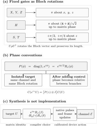
One-qubit gates admit several complementary descriptions. Fixed gates select particular rotations or basis changes; and have the same isolated-qubit action but differ by a global matrix phase; a general unitary can be reduced to Euler rotations and then compiled into calibrated pulses and frame updates. The implemented device action is generally a noisy channel , not the ideal matrix .
Bloch-Sphere Action
Section titled “Bloch-Sphere Action”Write
Under a unitary ,
where . One convenient definition is
This representation makes several facts immediate:
- unitaries preserve , purity, and angles between Bloch vectors;
- no isolated one-qubit unitary can turn a mixed state into a pure state;
- and give the same ;
- and are the two representatives of the same spatial rotation;
- gate composition maps to rotation composition in the same operator order.
The Bloch sphere is exact for one qubit, but it does not scale into a complete picture of a multi-qubit state. A local one-qubit gate acting on one part of an entangled state still has a matrix on that subsystem, yet the joint state lives in a tensor-product space. Local unitaries preserve bipartite entanglement measures even while they change local measurement statistics and correlation axes.
Global Phase Can Become Relative Phase
Section titled “Global Phase Can Become Relative Phase”State-vector phase
Section titled “State-vector phase”The state vectors
represent the same ray. By contrast,
are generally different rays because only one branch was rephased. Their relative phase changes interference and equatorial measurement probabilities.
Gate phase
Section titled “Gate phase”Let
Then the isolated channels agree, . Now define a controlled operation with the control as the first tensor factor:
Then
so the two controlled gates differ by a phase gate on the control. This is why replacing by is harmless for a standalone target but not automatically harmless after adding a control. Exact phase conventions are part of a reusable gate definition.
Composition and Useful Identities
Section titled “Composition and Useful Identities”The most reliable way to simplify a short gate sequence is to choose one representation and keep the order explicit:
- multiply exact matrices when phase matters;
- conjugate Pauli operators for basis-change questions;
- compose rotations for Bloch-vector questions;
- act on basis states for simple circuit semantics.
For example, means acts first:
But
The two sequences differ because and do not commute.
Useful inverse and power relations include
The last identity holds without a Baker–Campbell–Hausdorff correction because both rotations have the same generator. Rotations about different axes generally do not commute.
Basis Changes for Preparation and Readout
Section titled “Basis Changes for Preparation and Readout”A basis change can move complexity from the measurement to a preceding gate. Suppose hardware measures after a unitary . The effective observable on the input is
With the conventions on this page:
| Desired input basis | Gates before readout | Total pre-rotation | Effective observable |
|---|---|---|---|
| none | |||
| , then |
For the last row,
This table specifies the temporal order as well as the matrix product. Writing only “use and ” is ambiguous because the gates do not commute.
The reverse viewpoint prepares cardinal states. Starting from ,
Preparation and readout circuits are related by adjoints, but a real experiment may assign different errors to preparation pulses, frame updates, and measurement. Gate identities alone do not certify state-preparation-and-measurement performance.
Arbitrary One-Qubit Gates
Section titled “Arbitrary One-Qubit Gates”Euler decomposition
Section titled “Euler decomposition”Every one-qubit unitary can be written
The angles are not unique at coordinate singularities or after periodic shifts. This is a coordinate decomposition, not a claim that a device literally executes three pulses in that form. A compiler may cancel neighboring rotations, absorb rotations into a frame, or choose another native basis. Gate Decomposition uses Euler factors as one-qubit leaves inside controlled, Cartan/KAK, dense-unitary, and finite-alphabet synthesis.
The decomposition also gives a direct state-preparation rule. For
one has
Thus two rotations prepare any pure qubit state from up to global phase. A general gate needs a third rotation because it must specify the action on an entire basis, not only on one input ray.
Software parameterizations
Section titled “Software parameterizations”Circuit languages often expose a three-angle universal gate, but names, angle order, signs, and global phases are not universal. The OpenQASM 3 specification, for example, defines a built-in three-parameter together with an explicit global-phase operation; compatibility gates inherited from earlier versions use related but phase-shifted conventions.
Before translating a matrix into software:
- read the versioned gate definition;
- check whether the equality is exact or only up to phase;
- verify basis and qubit ordering;
- test the action on both and ;
- retain the documented phase when the gate may later be controlled.
From Ideal Matrix to Physical Control
Section titled “From Ideal Matrix to Physical Control”An ideal gate symbol names a target unitary. A physical device realizes time evolution generated by a control Hamiltonian, often modeled in an appropriate rotating frame as
The resulting propagator is
For a constant direction and pulse area
this reduces to in the ideal rotating-frame model. Detuning, leakage, crosstalk, finite bandwidth, decoherence, and calibration drift turn the implemented operation into a channel that only approximates the target.
A named gate need not correspond to a dedicated physical pulse. In many driven-qubit platforms it can be implemented as a software frame update that changes the phases of later drives. Such a virtual Z gate can be effectively instantaneous in the control schedule, but it still changes the interpretation of subsequent axes and must be tracked consistently. Other platforms may implement the same logical matrix by different controls.
Keep four layers separate:
| Layer | Object | Question |
|---|---|---|
| Logical | ideal matrix | What transformation is intended? |
| Compiled | sequence in a native gate set | How is decomposed for this target? |
| Scheduled | pulses, frame updates, and timing | What controls are issued and when? |
| Implemented | noisy channel | What transformation did the device realize? |
Rabi and Ramsey Control develops the driven dynamics. A later quantum-information page will own device-level error models; until then, Quantum Channels and Noise supplies the channel framework.
Verification Checklist
Section titled “Verification Checklist”For an unfamiliar claimed one-qubit gate:
- Unitarity: verify .
- Basis action: compute and .
- Phase claim: decide whether equality is exact or only projective.
- Bloch action: evaluate for .
- Composition: preserve right-to-left matrix order.
- Control context: do not discard a phase before adding a control.
- Implementation: distinguish the ideal matrix from a native instruction, pulse, or measured channel.
For two ideal matrices , a quick test for equality up to phase is
This criterion assumes both matrices are unitary. It says their isolated channels agree; it does not establish that two noisy implementations have the same error process.
Common Mistakes
Section titled “Common Mistakes”- Using and thereby doubling the intended Bloch rotation.
- Calling and exactly equal rather than equal up to .
- Dropping a gate phase before forming a controlled version.
- Reading a left-to-right circuit as a left-to-right matrix product.
- Treating as a random-number operation instead of a coherent basis change.
- Forgetting the phases in the action of .
- Assuming the logical , , and axes are literal laboratory directions.
- Comparing software gate names without checking versioned definitions.
- Treating an ideal unitary matrix as a calibrated physical pulse.
- Inferring that a one-qubit gate can create entanglement from an initially separable multi-qubit state; local unitaries alone cannot.
Exercises
Section titled “Exercises”1. Pauli action with phases
Section titled “1. Pauli action with phases”For
compute , , and . Verify .
Solution
Direct matrix action gives
Applying first and then ,
The phase is part of the exact operator identity.
2. Phase gate versus z rotation
Section titled “2. Phase gate versus z rotation”Show that . Then show that their controlled versions differ by on the control qubit.
Solution
Multiplying by gives
Using
with and gives
The factor is a relative phase between the control branches and cannot generally be discarded.
3. Gate order on a cardinal state
Section titled “3. Gate order on a cardinal state”Starting from , compare with . Give both final Bloch vectors.
Solution
Since ,
whose Bloch vector is . On the other hand, , so
whose Bloch vector is . The rightmost gate acts first.
4. Prepare an arbitrary pure qubit
Section titled “4. Prepare an arbitrary pure qubit”Prove that
prepares the Bloch-sphere state with polar angle and azimuth , up to global phase.
Solution
First,
Applying gives
The prefactor is global. The remaining state has the required polar and azimuthal angles.
5. Hadamard conjugation
Section titled “5. Hadamard conjugation”Verify and by matrix multiplication. Use the result to explain why applying , measuring , and forgetting the final state realizes an -basis measurement of the input.
Solution
Direct multiplication gives
and
The probability of outcome after applying is
These are exactly the -measurement probabilities of the original state.
6. Pulse area and sign check
Section titled “6. Pulse area and sign check”Suppose a rotating-frame control Hamiltonian is constant:
for a duration . Find the ideal gate. Which duration produces up to global phase, and what is that phase?
Solution
The propagator is
Choose . Then
Thus produces the same isolated-qubit channel as , with matrix phase . That phase must be restored or tracked if this pulse-defined operation is inserted into a controlled construction.
Where to Go Next
Section titled “Where to Go Next”- Circuit Model fixes wire order, gate embedding, composition, measurement, and resource conventions.
- Multi-Qubit Gates continues with controlled, exchange, and Toffoli gates, parity measurements, and entangling capability.
- Controlled Operations determines when an otherwise global target-gate phase becomes a branch-relative phase and audits the control and access assumptions; this page retains the base one-qubit phase conventions.
- Universal Gate Sets distinguishes exact from approximate universality and develops Clifford+ synthesis.
- Gate Decomposition turns Euler factors and larger structured unitary targets into verified circuits over a declared alphabet.
- Bloch Sphere for Quantum Information develops states, measurements, tomography, unitary rotations, and channels in Bloch coordinates.
- Quantum Gates Formula Card and Quantum Gates Reference Table provide compact lookup forms.
- Unitary Operators and Matrix Functions and Exponentials supply the linear-algebra machinery.
- Spin Rotations derives the half-angle formula and double cover.
- Projective Hilbert Space explains why state vectors differing by global phase define the same pure state.
- Rabi and Ramsey Control connects rotation gates to driven two-level dynamics.
- Pulse-Level Control connects those rotation semantics to calibrated frames, sampled waveforms, schedules, and controller artifacts.
- Quantum Information Roadmap places one- and multi-qubit gates before universality and algorithms.
References
Section titled “References”- M. A. Nielsen and I. L. Chuang, Quantum Computation and Quantum Information, 10th anniversary ed., Cambridge University Press, 2010, doi:10.1017/CBO9780511976667.
- A. Barenco, C. H. Bennett, R. Cleve, D. P. DiVincenzo, N. Margolus, P. Shor, T. Sleator, J. A. Smolin, and H. Weinfurter, “Elementary gates for quantum computation,” Physical Review A 52, 3457–3467, 1995, doi:10.1103/PhysRevA.52.3457.
- J. Preskill, Lecture Notes for Physics 219/Computer Science 219: Quantum Computation, Chapter 5, California Institute of Technology, course materials.
- OpenQASM contributors, OpenQASM 3 Specification, “Gates” and “Standard library,” versioned specification.
- D. C. McKay, C. J. Wood, S. Sheldon, J. M. Chow, and J. M. Gambetta, “Efficient gates for quantum computing,” Physical Review A 96, 022330, 2017, doi:10.1103/PhysRevA.96.022330.
- J. J. Sakurai and J. Napolitano, Modern Quantum Mechanics, 3rd ed., Cambridge University Press, 2020, doi:10.1017/9781108587280.
- N. D. Mermin, Quantum Computer Science: An Introduction, Cambridge University Press, 2007, doi:10.1017/CBO9780511813870.